| Solution ID | sk53980 |
| Product | IPSec VPN |
| Version | All |
| Platform / Model | All |
| Date Created | 13-Sep-2010 |
| Last Modified | 06-Aug-2017 |
Introduction
This document describes how to set up a VPN connection between a Check Point gateway and a 3rd party Interoperable Device.
There are 3 main sections:
- New VPN Check Point Gateway configuration.
- Interoperable Device and VPN community configuration.
- Required Firewall Rule Base definition.
Table of Contents
- Configuring Check Point Security Gateway with VPN
- Configuring the Interoperable Device and VPN community
- Defining VPN encryption domain for Interoperable Device
- Creating a rule for the traffic
- Completing the procedure
- Troubleshooting
- Related solutions and documentation
Configuring Check Point Security Gateway with VPN
Note: If you have a fresh installed Check Point Gateway that is also defined as Security Management server and should be used as a VPN Gateway, start from step 6.
In most cases this Gateway has the icon and is named "gw-<number>".
In most cases this Gateway has the
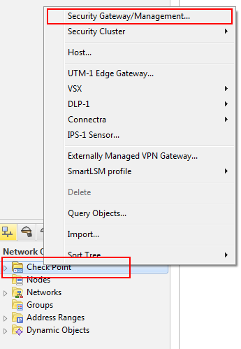
To create Check Point Security Gateway:
- In the Network Object right-click on Check Point and Security Gateway/Management.
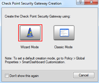
- Click Wizard Mode
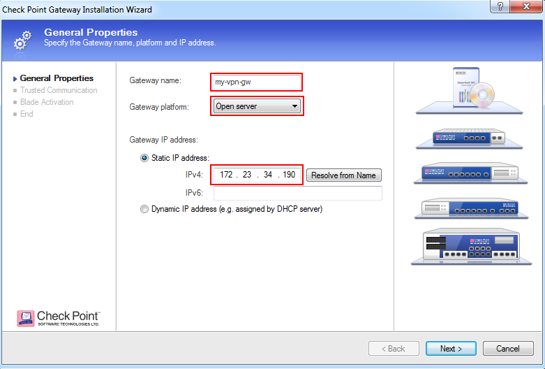
- Enter
- Gateway name
- Gateway platform
- IPv4 address
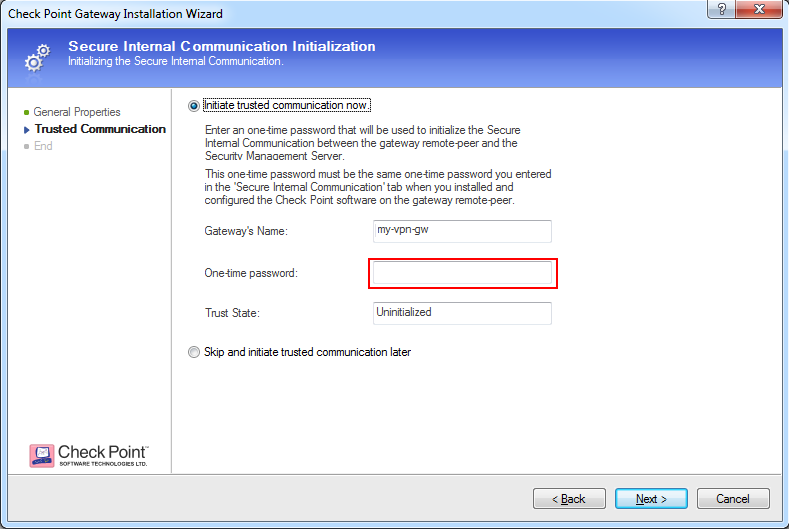
- Click Next and enter the one-time password as defined on Check Point Security Gateway during installation.
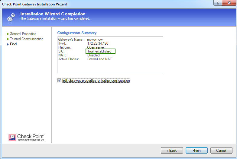
- Click Next after trusted communication established, then click Finish.
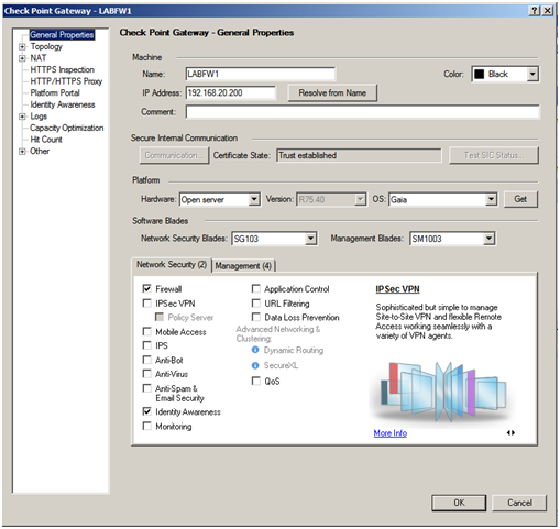
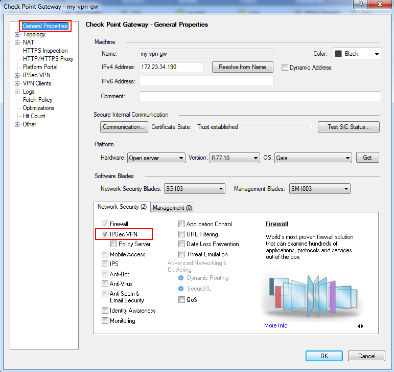
- In the General Properties window of your Security Gateway, make sure the 'IPSec VPN' checkbox is selected.
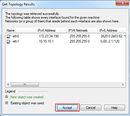
- Define VPN encryption domain for your Gateway. Make sure that you have at least one internal and one external interfaces. VPN encryption domain will be defined to all networks behind internal interface.
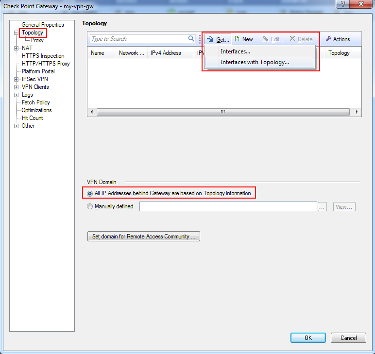
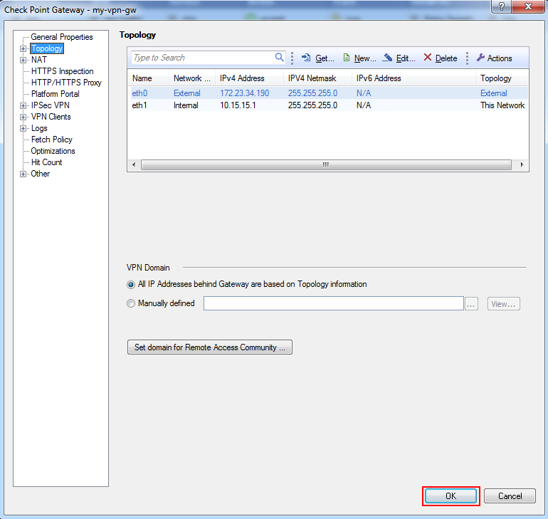
- Click Accept
- Click OK and close the Gateway dialog
Configuring the Interoperable Device and VPN community
Create an object to represent the peer gateway.
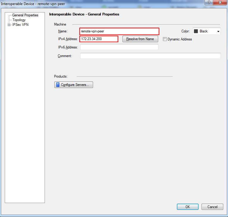
- Right-click the white space of Network Objects and select: New -> Others -> Interoperable Device
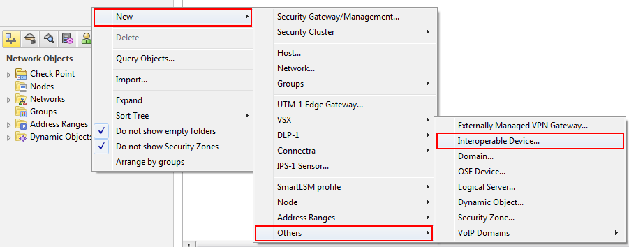
- Give the gateway a name, IP address, and (optional) description in the properties dialog window that is displayed and click OK.
- In the SmartDashboard IPSec VPN tab, right-click in the open area on the top panel and select: New -> Meshed Community.
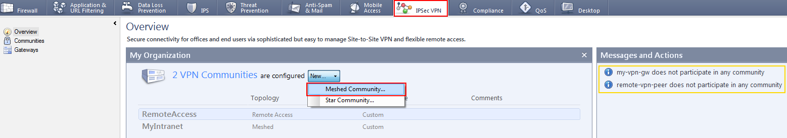
- A Meshed Community Properties dialog pops up.
In the General menu, enter your VPN community name: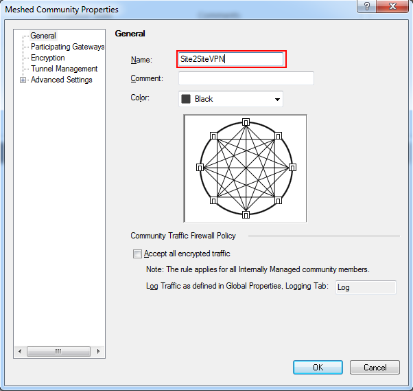
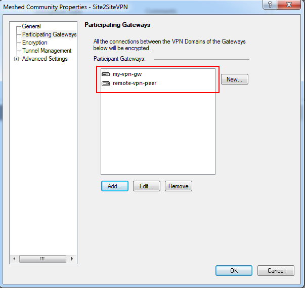
- In the Participating Gateways menu click: Add, select your both gateways objects, and click OK.
- In the Encryption menu, you can change the Phase 1 and Phase 2 properties.
You can also define which IKE version should be used. For IKEv1 leave the default, for IKEv2 select IKEv2 only.
Note: Make a note of the values you select in order to set the peer to match them.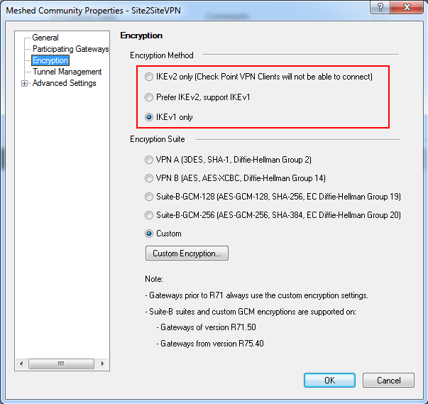
- In the Tunnel Management menu you can define how to setup the tunnel.Note: The recommended tunnel sharing method is one VPN tunnel per subnet pair (default).
This shares your network on either side of the VPN and makes the Phase 2 negotiation smooth. It also requires fewer tunnels to be built for the VPN.
If you need to restrict access over the VPN, you can do that later through your security Rule Base. - For preshered authentication, expand the Advanced Settings menu and select: Shared Secret.
Select the 'Use only Shared Secret for all External members' checkbox.
Select your peer gateway from the entries in the list below and click Edit to edit the shared secret.Note: remember this secret, as your peer will need it to set up the VPN on the other end.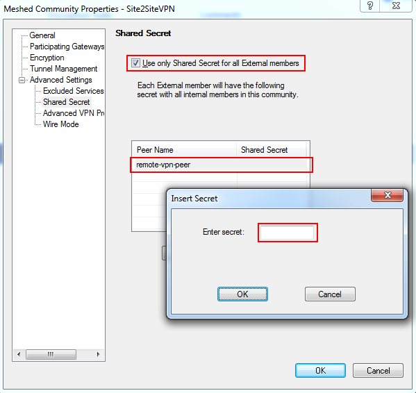
- Expand the Advanced Settings menu and select: Advanced VPN Properties. Here, you can modify the more advanced settings regarding Phase 1 and 2.Note: Keep note of the values used. It is also a good idea to select:
Disable NAT inside the VPN community so you can access resources behind your peer gateway using their real IP addresses, and vice versa. - Click OK on the VPN community properties dialog to exit back to the SmartDashboard.
You may see the following message: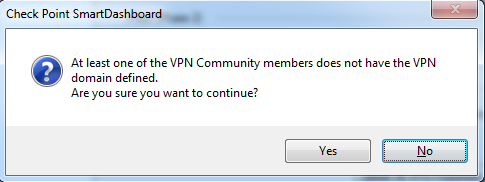
- We are about to address the VPN domain setup in the next section, so click Yes to continue.
Now you can see your VPN community defined: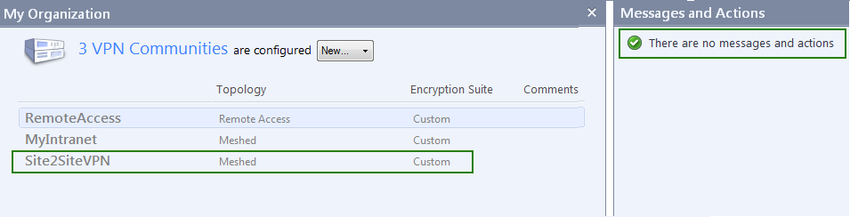
Defining VPN encryption domain for Interoperable Device
You now need to define your VPN encryption domains.
If you have not already done so, create network objects to represent your local networks and the peer networks they will be sharing with you.
To define VPN encryption domains:
If you have not already done so, create network objects to represent your local networks and the peer networks they will be sharing with you.
To define VPN encryption domains:
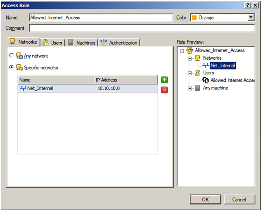
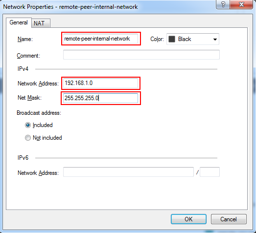
- From the Network Objects menu, right click on Networks and select Network to define a new network. In the following image, we are creating a network to represent our peer's internal network that they will be sharing with Check Point VPN gateway:
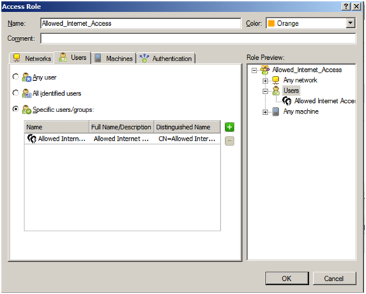
- If you or your peer is sharing more than one network over the tunnel, create groups to represent each side's VPN domain. From the Network Objects menu, right click on Groups, select Groups and then Simple Group...In this example, only one network is shared, so the group will have only one object included, but you can put as many networks in this group as you want to share.
Note: it is important not to add groups within a group as this can impact performance. Make sure the group is "flat".
Give your group a meaningful name such as: Local_VPN_Domain.
Click OK once you have added all of your local networks and then repeat the procedure to create a group to represent your peer's shared networks. - Open the properties for the peer gateway and select the group/network that represents its VPN domain:
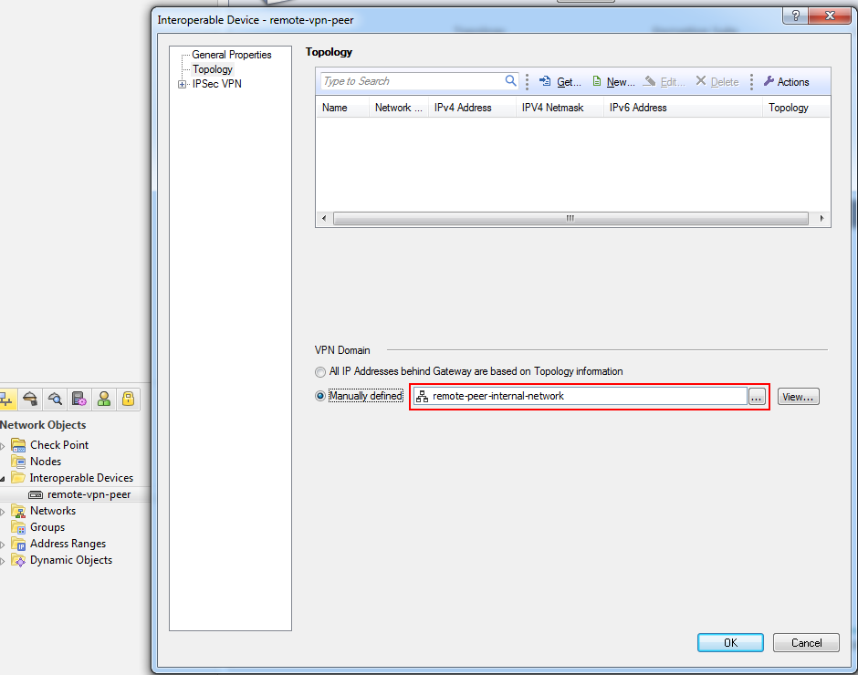
- Click OK to complete the peer gateway configuration.
Creating a rule for the traffic
Now, you have both objects set up for VPN and you have defined your community. All that is left is to create a rule for the traffic.
Here is where you should restrict access if it is required.
To create a rule for the traffic:
- To allow VPN traffic, you should add the relevant rules to your Firewall Rule Base.
Navigate Rule Base, Firewall -> Policy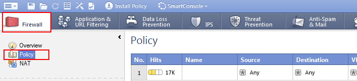
- Decide where in your rule base you need to add your VPN access rule and right click the number on the rule just above where you want it and select: Add Rule -> Below.
- You should explicitly set the VPN community in the VPN column on your rule, you have created before.
In the VPN column, right-click the Any Traffic icon and select: Edit Cell....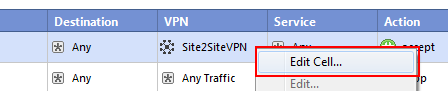
Select the: Only connections encrypted in specific VPN Communities option button and click Add.
Select the VPN community created in the above steps and click OK and then OK again.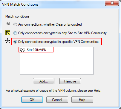
- In this example, we are allowing any service/any host across the tunnel in both directions. Your rule should now show the VPN community in the VPN column:

Completing the procedure
- Install the policy to your local Check Point gateway.
- Once the remote side has setup their VPN to match, verify that you have secure communication with their site.
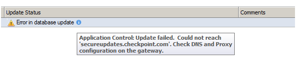
Troubleshooting
- Problem: Traffic is dropped by 3rd party gateway and main IP configuration was defined to internal IP address for Check Point Gateway.
Generally, it is recommended to define main gateway IP address with external IP (in Check Point Gateway – General Properties). In some cases, for example: StandAlone gateway, administrator wants to define main IP address as internal IP in order to allow managing from internal network.
In this case, VPN link selection should be changed.
Open Check Point gateway properties dialog, select IPSec VPN -> Link Selection and click Source IP address settings...
In opened dialog, select Selected address from topology table and select relevant external IP address, used by remote peer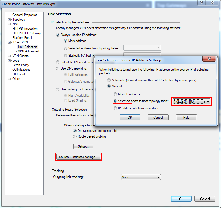
- Problem: IKE keys were created successfully, but there is no IPsec traffic (relevant for IKEv2 only).
In some cases, remote peer chooses NAT-T encapsulation but Check Point gateway sends traffic without this encapsulation. As a result, a remote peer drops the IPsec traffic since it expecting NAT-T.
There are two workarounds available to resolve this problem:
- If IKEv2 is required by remote peer, NAT-T should be disabled.
To do so, open Check Point gateway properties dialog, select IPSec VPN -> VPN Advanced and clear 'Support NAT traversal (applies to Remote Access and Site to Site connections)' checkbox: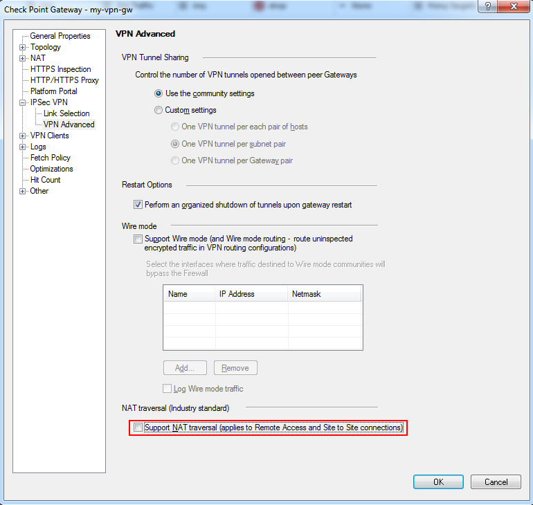
Note: This solution is not suitable for gateways participating in the Remote Access community. - If IKEv2 is not required, in the SmartDashboard, go to Community -> Encryption and change configuration to IKEv1.
- If IKEv2 is required by remote peer, NAT-T should be disabled.